Procurement teams face a massive hidden risk when sourcing modern charging hardware. Many suppliers aggressively market a 100W PD USB C Hub claiming flawless operation. However, these devices often throttle badly under sustained load. They might also reserve excessive power just for internal operations, misleading buyers.
This dangerous gap between theoretical spec sheets and real-world implementation quickly leads to client dissatisfaction. As a result, brands suffer skyrocketing return rates and permanent reputational damage. Sourcing reliable B2B charging hardware requires moving past surface-level claims. You must demand rigorous technical validation to protect your brand.
You need a strong, evidence-based framework to audit your supplier claims effectively. We will guide you through verifying power delivery stability. You will learn how to confirm critical safety compliance before authorizing mass production. Master these steps to secure high-quality products consistently.
Key Takeaways
- Verifying a 100W PD USB C Hub requires load testing at maximum capacity (20V/5A) to identify thermal throttling and voltage drops.
- True USB C power delivery in hubs must account for internal internal power consumption; a 100W input typically yields a maximum of 85W-90W to the host device.
- Importers must demand USB-IF compliance and PD 3.0/3.1 certification to mitigate safety risks and navigate cross-border trade regulations.
- Effective OEM hub quality control requires auditing the supplier's PCBA design, E-Marker chip integration, and dynamic power allocation algorithms.
The Business Risk of Unverified Power Delivery Claims
A massive gap exists between theoretical lab specifications and real-world implementation. A supplier might state a 100W charging capacity on their datasheet. This number rarely guarantees continuous 100W output during heavy daily use. Lab environments often test devices under perfect thermal conditions for mere seconds. Real users push these devices for hours. If a hub cannot sustain its maximum output, you face severe product failures.
Unreliable suppliers often cut corners to increase their profit margins. You must spot these dangerous shortcuts early. Common supplier cost-cutting measures include:
- Counterfeit E-Marker chips: Bundled cables lacking genuine chips fail to negotiate safe 5A currents.
- Inadequate thermal dissipation: Poor designs lead to aggressive power throttling after just 10 to 15 minutes.
- Poorly coded PD controllers: Cheap chips fail to negotiate optimal voltage profiles correctly.
These hidden failures trigger immediate safety hazards for end users. Devices overheating can easily melt internal components or damage expensive laptops. Consequently, these failures void product warranties prematurely. When warranties fail, OEM brand reputation takes a massive hit. Negative reviews accumulate quickly. You will see your Return Merchandise Authorization (RMA) rates skyrocket. You must implement strict technical safeguards to prevent these exact scenarios.
Essential 100W PD Performance Test Protocols for OEMs
You need a strict evaluation baseline before approving any supplier prototype. A successful 100W PD performance test requires maintaining a 20V/5A output continuously. The device must sustain this load for at least one hour. Furthermore, it must never drop the power negotiation during this period. Any voltage dip indicates underlying hardware instability.
To capture accurate data, testing engineers utilize specialized equipment. Programmable DC electronic loads simulate extreme usage scenarios perfectly. Specialized USB power meters capture real-time voltage and current curves accurately. You should structure your testing sequence carefully.
- Connect the device to a programmable DC electronic load.
- Initiate fixed voltage rules testing sequentially (5V, 9V, 12V, 15V, 20V).
- Trigger Programmable Power Supply (PPS) dynamic stepping to verify micro-adjustments.
- Monitor the data log for sudden voltage drops over a 60-minute duration.
Below is an essential testing reference table for OEM buyers.
| Testing Phase | Required Equipment | Success Criteria |
| Fixed Voltage Output | USB Power Meter | Stable negotiation at 5V, 9V, 12V, 15V, and 20V. |
| Sustained Maximum Load | DC Electronic Load | Maintains 20V/5A for 60+ minutes seamlessly. |
| Dynamic Stepping (PPS) | Protocol Analyzer | Smooth voltage transitions without resetting connections. |
| Cross-Platform Handshake | Test Laptops (Mac/Win) | Instant recognition across diverse host architectures. |
Beyond raw power, you must test handshake compatibility rigorously. A hub must negotiate power protocols correctly across diverse host operating systems. Test your samples using macOS, Windows, and ChromeOS devices. Ensure compatibility across different silicon architectures, including Intel, AMD, and Apple Silicon. A hub failing to negotiate proper charging profiles across these systems remains unmarketable.
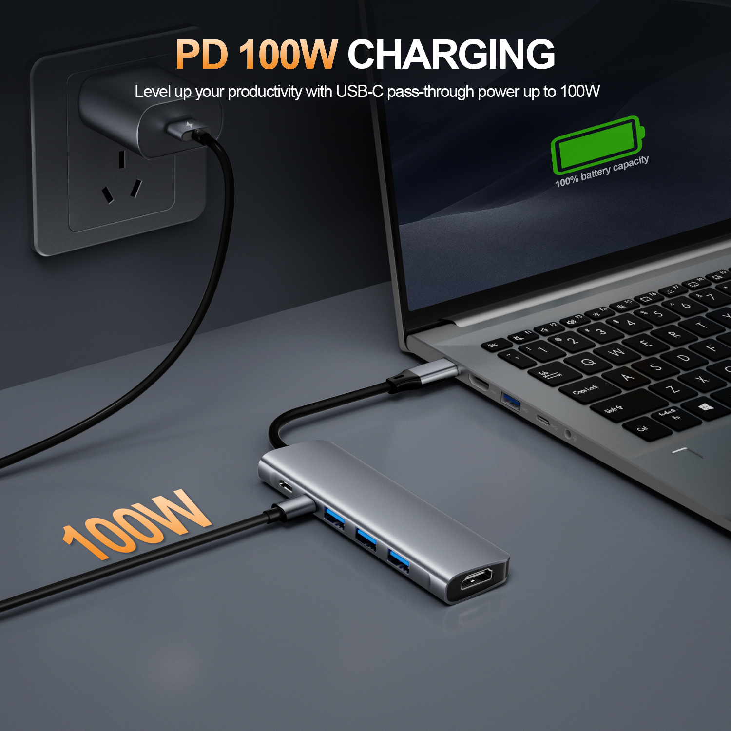
Evaluating Thermal Management and Dynamic Power Allocation
Sustained USB C power delivery inevitably generates substantial internal heat. You must evaluate this correlation closely during procurement. A compact chassis handling 100 watts of electricity acts like a small heater. If the internal temperatures rise too high, safety mechanisms automatically throttle the power output. This drops charging speeds drastically.
You must assess the supplier's heat dissipation architecture thoroughly. Request detailed PCBA layout schematics from your factory partners. Good layouts separate the power delivery controller from data processing chips. Next, verify the efficacy of their thermal padding. High-quality thermal pads transfer heat from the PCB directly to the aluminum enclosure. We highly recommend using infrared thermal imaging cameras during peak load tests. Surface temperatures should ideally remain below 50°C (122°F) to ensure safe handling.
Power reserving mechanics often confuse end users. You must clarify the standard "100W Input vs. 85W Output" rule. Hubs consume electricity internally to operate. A hub requires roughly 15W to power its internal chips. It also needs power to drive peripheral ports safely. Therefore, feeding 100W into the hub yields a maximum of 85W to the host laptop.
You must audit a PD charging hub's dynamic power allocation logic. Peripheral ports, including USB-A, HDMI, and Ethernet, require stable current. When a user plugs a hard drive into a USB-A port, the hub reallocates power dynamically. Poorly designed algorithms will momentarily interrupt the laptop's charging connection during this process. Rigorous testing ensures peripherals receive adequate current without resetting the host device's power handshake.
USB-IF Compliance and Regulatory Certification Standards
Raw performance metrics mean nothing without official compliance backing them. You must view supplier claims through highly authoritative lenses. Safety standards exist to prevent catastrophic hardware damage. Independent laboratory testing validates a manufacturer's internal engineering quality. Relying solely on a supplier's internal testing reports exposes your business to massive liability.
You must mandate PD 3.0 or PD 3.1 certification. USB-IF certification is an absolute necessity for mitigating severe risks. Uncertified hubs frequently suffer from protocol mismatches. These mismatches can force incorrect voltages into fragile laptop batteries. Overvoltage scenarios cause irreversible damage to consumer electronics. Certified controllers guarantee strict adherence to industry safety parameters.
Global distribution introduces complex market-specific trade barriers. Importers need verifiable documentation to clear customs smoothly. You must secure valid CE certifications for European markets. The FCC mark is non-negotiable for North American distribution. Furthermore, RoHS compliance ensures your products remain free of hazardous materials. As power demands increase, you might also need EPR (Extended Power Range) documentation for future-proofing your catalog.
Apply healthy skepticism in action during the supplier vetting process. Factories often provide fraudulent or expired certification numbers. You must cross-reference every supplier-provided document with official regulatory databases. Check the USB-IF integrator list manually. Verify CE and FCC registration numbers through official testing laboratory portals. Weeding out fraudulent claims early saves countless hours of legal headaches later.
Structuring OEM Hub Quality Control in Your Supply Chain
Moving from prototype testing to mass-production consistency requires robust shortlisting logic. A golden sample might perform flawlessly on your desk. However, producing ten thousand identical units introduces severe manufacturing variances. You need a structured auditing protocol to guarantee every batch meets your standard.
Supplier audit requirements should focus heavily on raw data. Do not accept summarized marketing graphs. Request the raw data logs from their factory burn-in tests. You should also ask for reports from their aging chambers. Furthermore, verify the factory's incoming quality control (IQC) procedures. They must rigorously test critical components upon arrival. If they do not verify incoming PD controllers and capacitors, their final product will suffer.
Establish strict Acceptable Quality Limit (AQL) standards for OEM hub quality control prior to shipment. Third-party inspectors should test power delivery parameters on the assembly line. Below is a recommended inspection chart for establishing your AQL framework.
| Inspection Parameter | Inspection Method | Acceptance Threshold |
| Component Verification | Visual / Schematic Check | 100% match with approved BOM. |
| E-Marker Validation | Cable Tester Analysis | Confirmed 5A/100W e-marker chip present. |
| Peak Thermal Load | Infrared Scan at 100W | Surface temp under 50°C after 2 hours. |
| Dynamic Allocation | Peripheral Plug Test | Zero host power resets during peripheral insertion. |
Take immediate next-step actions to secure your supply chain. Draft a highly specific engineering sample request today. Explicitly demand a detailed PD negotiation log alongside your physical sample. Request a comprehensive thermal performance graph covering a 4-hour continuous load. Suppliers hesitating to provide this data are hiding engineering flaws. Transparent factories will gladly share their stress-test methodologies.
Conclusion
Sourcing a reliable 100W PD hub demands far more than reading promotional specifications. You must prioritize empirical testing of thermal stability and power allocation logic. Ignoring these technical realities severely compromises product safety. Furthermore, confirming regulatory compliance shields your brand from cross-border trade disruptions.
Credible OEM partners embrace rigorous validation processes. They will transparently share their stress-test methodologies and compliance documentation without hesitation. We strongly advise procurement teams to elevate their vetting standards immediately.
- Mandate a standardized 100W stress-test requirement in your next supplier Request for Quotation (RFQ).
- Require raw thermal imaging data for all future engineering samples.
- Establish strict third-party AQL inspections focused on power negotiation stability.
- Verify all USB-IF and regional safety certificates through independent databases.
FAQ
Q: Why does a 100W PD USB C Hub only deliver 85W to my laptop?
A: Hubs reserve 10W-15W of the input power to operate their internal chips and supply power to peripheral ports (like USB-A and HDMI). This is a required safety standard, not a defect.
Q: How do E-Marker chips affect 100W PD performance tests?
A: An E-Marker chip validates that a cable can safely carry 5 Amps of current. Without it, the PD controller will automatically cap the power delivery at 60W (3 Amps) to prevent overheating.
Q: What is the difference between PD 3.0 and PD 3.1 in an OEM hub?
A: PD 3.0 caps at 100W (20V/5A). PD 3.1 introduces Extended Power Range (EPR), allowing up to 240W. For a strictly 100W hub, PD 3.0 compliance is sufficient, but PD 3.1 readiness indicates forward-compatible engineering.
Q: What should I look for in a supplier's burn-in test report?
A: Look for sustained continuous load duration (typically 2-4 hours at full 100W), ambient temperature controls, and logged data proving zero voltage drops or connection resets during the test cycle.


